 |
|
In the present version, radio program in the best CD quality sound are emitted (see techn. Data). The coding switch on the circuit board are not needed in conjunction with the included LCD display because the frequency is set with two external probes only If a longer range transmission power are achieved through increased, so a corresponding output RF amplifier (power amplifier) are added. Thus, transmission powers are possible up to several kW. |
|
|
|
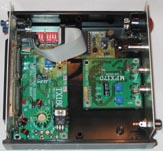
The presented single individual modules are combined: in our standard package would be complete following execution model as according to your wishes to the 19-inch rack, fits to your existing equipment. |
 |
|||||||
 |
|||||||
 |
|||||||
|
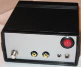
Back with jacks for inputs and outputs: Subject to technical changes |
|||||||
|
from left to right: antenna jack, RCA inputs on the left and right, RDS input, supply 22-24 Volt DC |
|
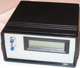
The complete unit is supplied phantom power supply and antenna including dimensions of the complete unit: 128mm x 63mm x 135mm. |
|||
|
Manual of the TX180 as PDF for Download and useful tips for the use of TX-Antenna |
|||
|
Also available, the stereo encoder for broadcasting transmission in stereo |
|
|
|
When ordering the encoder it is already completely wired to the transmitter, delivered This is the newest component of this attractive offer to a compact unit rounds |
|
|
||||||||||||||||||||||||||||||||||||||||||||||
|
This optional circuit board and the associated software that enables text messaging program running appear to be in the transmitter and your ID will display on any RDS-enabled receiver shown in. * To reach even a useful tip: Not only the output power essentially determines the range, but the execution (simple dipole, cross dipole or directional antenna) and the position of the transmitting antenna. For example, transmission power between 1 Watt and 15 Watt from barely noticeable effect, compared to when the antenna above ground meters or 15 meters above ground mounted other important information on transmission antennas please see the following Link § at last still note: This is a tax-radio stations. Unauthorized use of this device, the EU punishable with hefty fines. You may not use this channel (without broadcasting license and frequency allocation of the Federal Network Agency and the local media authority) with only a 50 - dummy run at the antenna output ohms for example, tests performed on radio receivers.Or a closed system in use (house antenna system) from which no radiation penetrates |
| [Home] [50nW Transmitter] [FM Transmitter] [Accessories] [WebShop] [Contact] [ZaraSoft] [§ § §] |